2.3. AFR MAP setting
Icon for Advanced mode
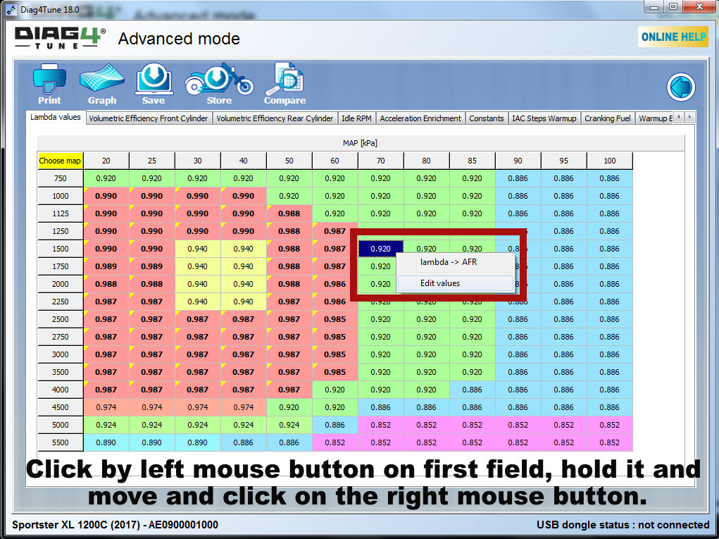
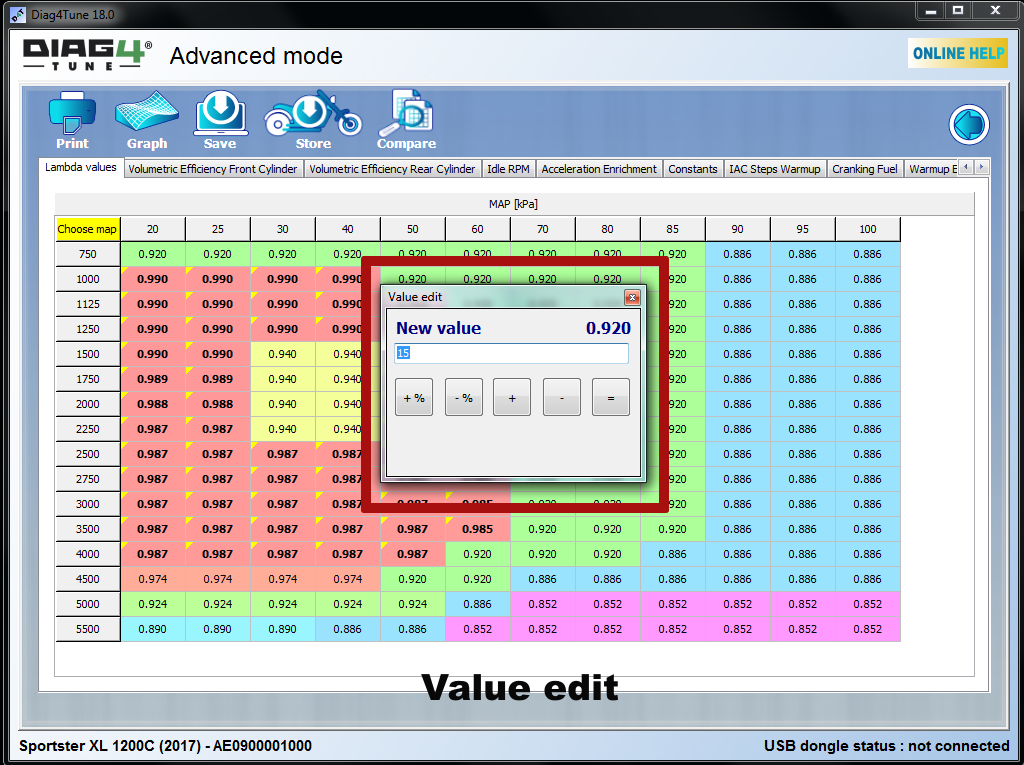
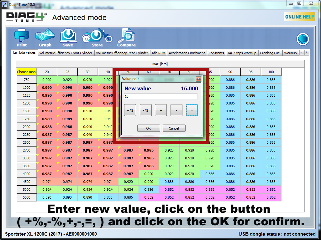
Manual settings Values

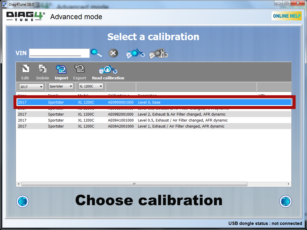
Advanced Mode is a tool to modify all available maps in this mode. This includes the AFR map, VE maps, ignition advance maps and RPM limiter. The use of the Advanced Mode for the optimisation of the fuel maps is a logical continuation of the VE measurements, you have actually measured how the engine (each of its cylinder)”breathes”.
Advanced mode allows you to manually change VE values, but there is no reason for it if you have measured and set the new current VE maps.
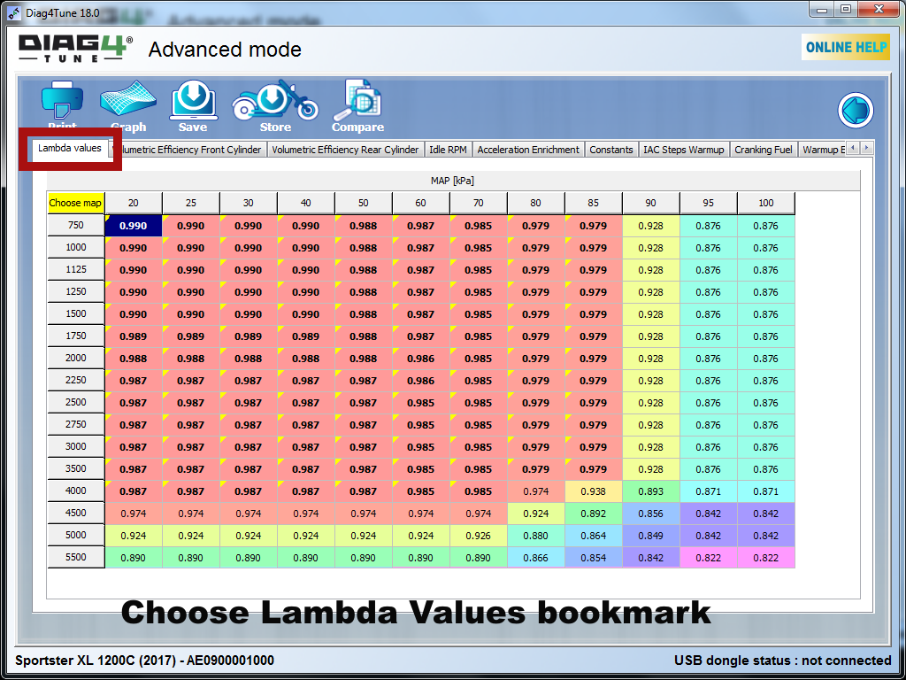
Having followed the proper process of fuel maps optimisation, the next step is to set the second important part of the fuel maps – the AFR map, i.e. the map of the target AFR values which is now the guiding principle for the EFI system to calculate fuel injection and therefore the actual AFR of the engine.
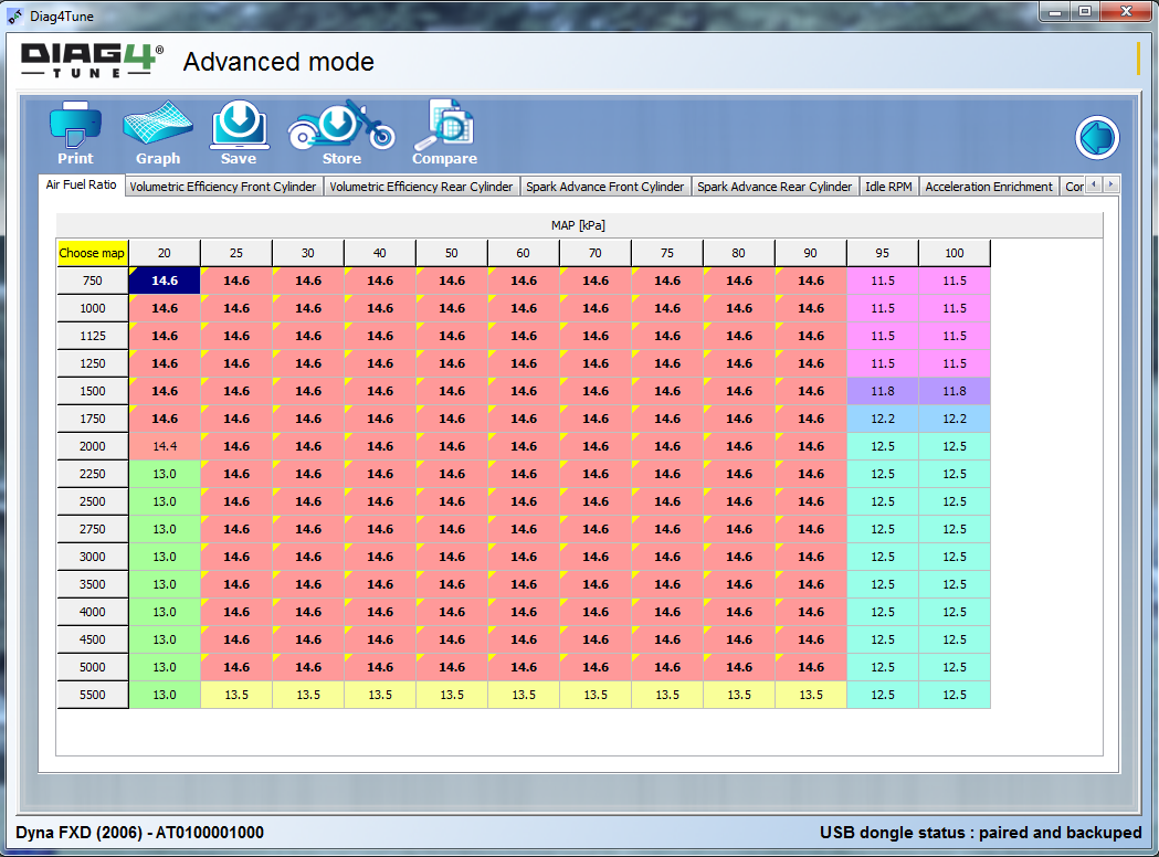
An example of a typical AFR map (XL 1200) map is shown on the left . The values of 14.6 are the engine modes where the EFI system sets stoichiometric ratio of the combustion controlled by built-in lambda sensors.
Lower AFR (richer mixture) is set only for extreme modes (high RPM and full throttle, MAP close to 100 kPa). In this case the main reason for using a rich mixture is better cooling of the engine in extreme modes and partly also increased power (as shown below). A relatively rich mixture is also set for closed throttle throughout the entire RPM range (MAP around 20 kPa). In this case, the reason is to suppress back-fire during deceleration. EFI maintains the mixing ratio well above the ignition limit so that the mixture burns out reliably and to prevent its accumulation in the exhaust. If it accumulated in the exhaust, there would necessarily be some random ignition of the mixture in the cylinder which would in turn ignite the unburned mixture in the exhaust with a strong acoustic manifestation.
The marginal modes described in the previous paragraph are not interesting in terms of tuning (unless our goal is to annoy a neighbour or their dog by occasional back-fire to the exhaust). Our region of interest should be the area where the target AFR is set to 14.6, i.e. we should focus on controlling the mixing ratio by closed loop of lambda sensors. This is undoubtedly the best way of control, in terms of engine emissions and more or less in terms of fuel consumption. However, it is obviously not optimal with regard to the achievable torque and engine power, which is illustrated by the following characteristics.

The pattern of maximum torque of the V-Twin engine, depending on the set AFR
These characteristics show the maximum torque curve of the V-Twin engine (which was always found in the speed range from 2500 to 3000 min-1) depending on the set AFR. The green curve represents the measurement at 100% throttle opening. The orange curve represents the maximum torque pattern in continuous throttle opening to 60%. The black curve shows the average value. The results of the measurement show that torque characteristics can be increased merely by appropriate setting of AFR.
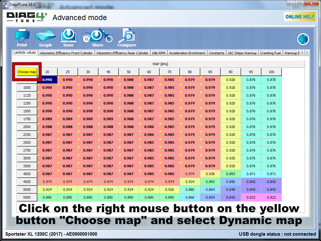
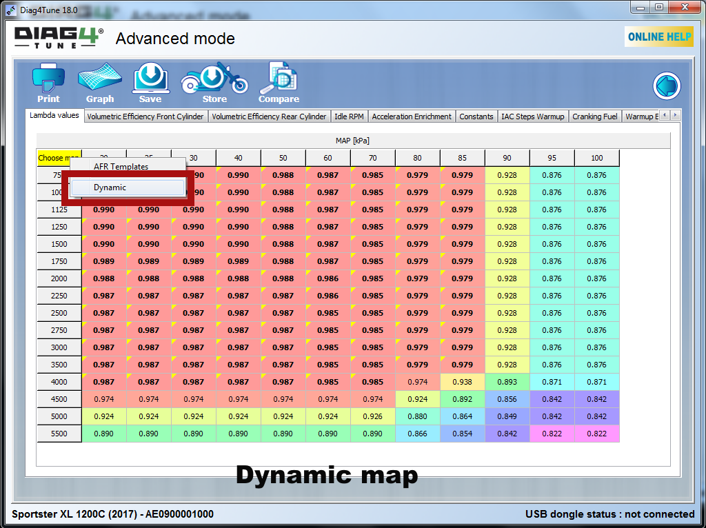
Further development has led us to the definition of ATAL Dynamic AFR maps. These maps are preset as menu templates on displaying the AFR map (see Demo movie 1). They are based on a compromise adjustment of maps. During road tests, we have defined an area that is used for steady cruising modes with minimal requirements for dynamic transitions. In these modes, it is not necessary to increase the torque characteristics and more focus is on the economy of operation, and thus optimal emission engine behaviour.
These modes generally range in the area defined by the MAP up to 60 kPa. In this case therefore, it is desirable to maintain the target AFR at 14.6, i.e. to control the mixing ratio by a closed loop of lambda sensors.
However, a completely different situation is in the area over 70 kPa as defined by MAP. This area represents the dynamic modes (acceleration) where it is desirable to use the maximum potential of the engine at the expense of economy of the operation. In these modes, therefore, the target values of AFR are to be set within the range from 12.5 to 13.5 – see figure below.
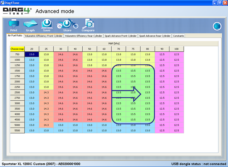
AN example (B) of a typical AFR map (XL 1200)
As mentioned in the introduction to tuning, the goal of tuning is not only increased performance characteristics. It also includes increased driving comfort. A well-known example is the behaviour of the XL 1200, the Evolution engine with an “open intake and exhaust” during urban cruising at 50 km/h (30 MPH), usually in the 3rd gear. The engine in these modes has occasional ignition gaps, which feels very uncomfortable and can sometimes even compromise driving safety (Slow Cruising Jerking). After much analysis, we have come to a conclusion than this is caused by unstable behaviour of closed control loop of the lambda sensor. As a remedy, to significantly suppress or completely eliminate these negative manifestations of the Evolution engine, it is advisable to set the AFR within the range of 13.5-14 (in the mode mentioned) in order to turn off the closed control loop. Maps equipped with this compensation mode are preset as menu templates as well, when displaying the AFR map (see figure below ). In any case, there is enough space for experiments for tuning operators. It is possible to look for the optimum value of the compensation AFR. We sometimes encounter a similar challenge in the case of the Twin Cam engines.
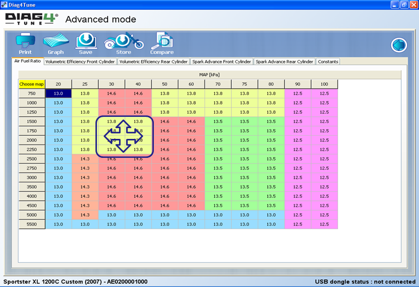
AN example (C) of a typical AFR map (XL 1200)